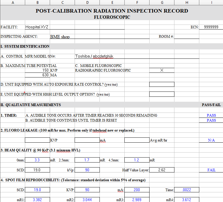
Post Calibration Radiation Inspection (PCRI) Fluoroscopic Sample Form
About
The Post Calibration Radiation Inspection (PCRI) is an inspection record for conventional radiography that details the step-by-step inspections and examinations prepared by trained agencies on the serviceability, quality assurance and control, as well as the functionality and operation of these ionizing radiation devices onto a document that complies with mandatory Federal, State, and Local Laws, Regulations & Performance Standards. The following PCRI is a mandatory requirement to be performed after new installations and repairs as well as during routine annual calibrations and safety inspections. The frequency for each test below are not final and technicians should always follow the most stringent standards and local policies.
System Identification
The system identification or equipment identification is the medical devices and its system components including the master control, room control, radiographic tube head's make and model, manufacturer name, and the device serial number used for FDA tracking and QA documentation. Additionally, we will input the systems highest kVp and mA that can be selected on dial and displayed on the the master control.
Visual inspection

Fluoroscopic parts. X-rays travel upward from the floor to the ceiling.
Visual Inspection, used in maintenance of medical equipment, means inspection of equipment and structures using all of the human senses such as vision, hearing, touch and smell and/or any non-specialized inspection equipment to include tape measures and/or magnetic angle measuring tool to verify proper operation.
Test Frequency
Annually
Test Tools
A tape measure and/or magnetic angle measuring tool.
Procedures
The following are some common verification inspections for general radiologic devices:
Pass or Fail
- CERTIFICATION LABELS ARE AFFIXED AND VISIBLE
- INDICATOR LIGHTS
- X-RAY TUBES FOR OIL LEAKS
- INTERLOCKS
(Door and table interlocks shall forbid exposure when in the open position. This includes the fluoroscopic primary barrier, which shall be in position for use in order for fluoroscopic exposure to be possible.)
- LOCKS and EXPOSURE SWITCHES
(At exposure times of 5 minutes the switch must terminate the exposure if manual pressure is removed.)
- VIEW BOXES
(The brightness of the view boxes used to check films after processing shall be within 15% of the brightness of the view boxes used by the radiologists to read the films.)
- LEAD APRONS, GLOVES, AND DRAPES
(Protective garments and drapes shall not have tears, which impair their radiation protection function.)
- BACKUP SAFETY TIMERS
- TABLE AND TUBE STAND MOTION
- BEAM LIMITING DEVICES (Manual and automatic mode)
- TABLE ANGULATION LIMIT SWITCHES
(Record angle in degrees using a magnetic angle measuring tool)
- DOES TUBE OVERLOAD PROTECTION CIRCUIT DISABLE EXPOSURE CIRCUIT?
- IS THE UNIT EQUIPPED WITH AUTOMATIC EXPOSURE CONTROL?
Radiation exposure during fluoroscopy is directly proportional to the length of time the unit is activated by a hand or foot switch. Unlike radiographic X-ray units that take snapshots, fluoroscopic units do not have an automatic timer to terminate the exposure after a predetermined length of time. Instead, the switch determines the length of the exposure, which ceases only after the foot switch is released.
- IS THE UNIT EQUIPPED WITH HIGH LEVEL ("BOOST") OUTPUT OPTION?
("Boost" produces higher tube current output from 10mA to 40mA. The maximum tabletop dose rate is limited to 20 R/min)
Timer Accuracy
The Exposure Timer directly affects the total quantity of radiation emitted from the tube an accurate exposure timer is critical for properly exposed radiographs and reasonable doses. Using an X-ray Quality Assurance meter such as RTIs Piranha you will measure multiple x-ray timing settings. Normally, the tolerance is within +/-5 milliseconds or the x-ray devices OEM listed tolerance.
Test Frequency
Semi-Annually
SID
12”
Technique Factors
60kVp, 100 mAs, no filtration (Air Kerma)
Test Tools
A X-ray Quality Assurance meter (e.g. RTIs Piranha or Barracuda)
Procedures
1. Place a QA meter upside down on top of table.
2. Set the Spot film in lowest position and lock in place.
3. Take a series of timing shots without any filtration.
4. Measure each with a stop watch and make sure an audible tone occurs after 5 minutes of continuous fluoroscopic exposure and record time.
Radiograpghic Leakage
Radiograpghic Leakage is the measurement of total radiation leakage in the room coming from the tube head after initial acceptance or a tube head replacement. In fluoroscopy, the tube is normally under the table and the x-ray beam is shooting upwards towards the ceiling.
Beam Quality
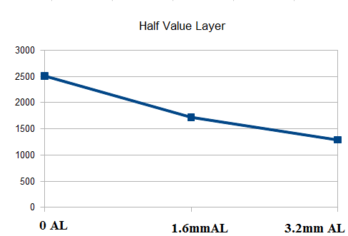
Graphic representation of the radiation field intensity being reduced by 1/2 as more Aluminum filters are added into the beam.
Beam Quality (Half Value Layer ) measures the X-ray beam thickness, depth, and penetration ability into the material at which the intensity of radiation entering it is reduced by 1/2. Each x-ray device has its own HVL limit posted on the FDA website.
Test Frequency
Annually
SID
12”
Technique Factors
90kVp, 200 mAs, 1000msec, filtration (0, 1.6mm Al, and 3.2mm Al)
Test Tools
A X-ray Quality Assurance meter (e.g. RTIs Piranha or Barracuda) and a HVL stand
Procedures
1. Place a QA meter upside down on top of table.
2. Set the Spot film and SID to 12” (highest position) then lock in place.
3. Take a series of eight shots without 0, 1.6 mm, and 3.2 mm Aluminum filtration at 90kVp, 200mA, and 1000 msec (1 second) settings. Make sure the Aluminum is on top of the table in the direction of the x-ray beam and the QA meter is placed on top of the Aluminum filter(s).
4. Hold fluoro exposure for 5 seconds. Hold times are repeatedly consistent with every exposure made.
5. Measure each exposure in milli-Roentgen (mR) / min and record.
6. Calculate the logarithmic value using this formula: ((1.6*LOG((2*F71)/B71))-((3.2*LOG((2*D71)/B71))))/LOG(F71/D71)
7. If HVL exceeds the maximum value, passed above 3.2 mm Al at 90 KeV. This is not within the accepted limits and additional filtration is required.
Spot Film Reproducibility
Reproducibility measures the X-ray tube spot film output and reproducibility (difference between the measured and nominal value) for high voltage, time, and patient dosage output.
Test Frequency
Annually
SID
12”
Technique Factors
90kVp, 200 mAs, .0022msec, no filtration (Air Kerma)
Test Tools
A X-ray Quality Assurance meter (e.g. RTIs Piranha or Barracuda)
Procedures
1. Place a QA meter upside down on top of table.
2. Set the Spot film and SID to 12” (highest position) then lock in place.
3. Take a series of eight timing shots without any filtration at 90kVp, 100mA, and 1000 msec (1 second) settings.
4. Measure each exposure in milli-Roentgen (mR) / min and record.
5. Calculate the average mR/min with a standard deviation of +/- 5%
Maximum Fluoroscopic Output
The maximum fluoroscopic output of each fluoroscope must be checked annually or after any maintenance that may affect patient dose parameters and safety. The maximum dose rate of the fluoroscopy unit is federally regulated as well as tested in manual and automatic mode(s) for units manufactured after 1 August 1974.
Test Frequency
Annually
SID
12”
Technique Factors
90kVp, 200 mAs, .0022msec, filtration (two lead vests)
Test Tools
A X-ray Quality Assurance meter (e.g. RTIs Piranha or Barracuda) and two lead shield vests
Procedures
Manual Mode
1. Place two acrylic pieces on both sides and a QA meter will be in the middle. This allows Bluetooth communication between the QA meter and the palm pilot for acceptable communication.
2. Set the SID to 12” and lock in place.
3. Place fluoro unit in manual mode. Hold times are repeatedly consistent with every exposure made.
4. Place bucky all the way to the right towards the foot of the x-ray machine. The spot film/Image Intensifier should be all the way to the left or head of the x-ray machine.
5. Place two lead vests over the acrylic and QA meter. This will drive the x-ray exposure to maximum fluoro output while protecting the Image Intensifier screen from damage.
6. Take a fluoro exposure at highest settings 120kVp at 250mA settings.
7. Hold fluoro exposure for 60 seconds. Hold times are repeatedly consistent with every exposure made.
8. Measure each fluoro exposure in milli-Roentgen (mR) / min and record.
9. The acceptable tolerance is that the measurement should not exceed 5 mR/min.
Automatic Mode
1. Place two acrylic pieces on both sides and a QA meter will be in the middle. This allows Bluetooth communication between the QA meter and the palm pilot for acceptable communication.
2. Set the SID to 12” and lock in place.
3. Place fluoro unit in automatic mode. In auto mode, the fluoro will auto-select the kVp and mA settings when a fluoro expsoure is made.
4. Place bucky all the way to the right towards the foot of the x-ray machine. The spot film/Image Intensifier should be all the way to the left or head of the x-ray machine.
5. Place two lead vests over the acrylic and QA meter. This will drive the x-ray exposure to maximum fluoro output while protecting the Image Intensifier screen from damage.
6. Take a fluoro exposure at highest settings 120kVp at 250mA settings.
7. Hold fluoro exposure for 60 seconds. Hold times are repeatedly consistent with every exposure made.
8. Measure each fluoro exposure in milli-Roentgen / minute (mR/min) and record.
9. The acceptable tolerance is that the measurement should not exceed 10 mR/min.
(note: If you have a high level output option then you will perform the same test along with verification of a continuous audible alarm.)
Minimum Shutter Size
The minimum field size at the greatest SID shall be equal to or less than 5 cm x 5 cm. On fluoroscopic systems with manual shutter controls, the x-ray beam shall not exceed the area of the largest image receptor with the manual shutter controls fully opened and both fixed as well as at varying fluoro and spot film SID adjustments..
Means shall be provided to reduce the x-ray field size to 5 cm x 5 cm or less at the maximum SID; or
- For image-intensified fluoroscopic equipment, neither the length nor width of the x-ray field in the plane of the image receptor shall exceed that of the visible area of the image receptor by more than three (3) percent of the SID. The sum of the excess length and width shall be no greater than four (4) percent of the SID.
- For rectangular x-ray fields used with circular image receptor , the error in alignment shall be determined along the length and width dimensions of the x-ray field which pass through the center of the visible area of the image receptor .
Procedures
1. Fully close collimator shutters.
2. Set the Spot film and SID to 12” (highest position) then lock in place.
3. Take an exposure.
4. Measure exposure area and record length and width. (must be 5 cm x 5 cm or less at the maximum SID)
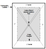
Field Size versus Intensifier


Fluoroscopic Beam Alignment Device by Fluke Biomedical
This measures the offset between the edges of the fluoro exposure and the Image Intensifier as a percentage of the SID. Field Size versus Intensifier reduces exposure to the patient in misaligned fluoroscopic Image Intensifier systems. Any portion of the field that falls outside the visible area of the image receptor does not contribute to the useful fluoroscopic image and can result in unnecessary exposure to the patient.
Test Tools
Fluoroscopic Beam Alignment Device
Procedures
If clipping is visible
1. Fully open the collimator shutters
2. If clipping is visible on all four sides and at various SIDs, enter "0" percent, record a passing result, and continue onto the next test.
If clipping is NOT visible


A misaligned flouro unit using a Fluoroscopic Beam Alignment Test Device
1. Place Fluoroscopic Beam Alignment Device on the table
2. Move the four brass strips up, down, left, and right 3 dots.
3. Make a fluoro exposure to ensure Fluoroscopic Beam Alignment Device alignment on screen.
4. Place 14 x 17 cassette under Fluoroscopic Beam Alignment Device.
5. Make a fluoro exposure and process cassette
6. The ends of the brass strips should correspond with the edges of the exposure as defined by the Fluoroscopic Beam Alignment Device. If not, the system is out of alignment.
7. Measure the total sum of the length and width offset of the actual field.
8. Use the following formulas:
8a. Length error = L1 + L2
8b. Width error = W1 + W2
8c. Length DIV/SID (% Error) = Length error/SID (12") * 100
8d. Width DIV/SID (% Error) = Width error/SID (12") *100
8e. Total Sum of length and width error = Length DIV/SID (% Error) + Width DIV/SID (% Error)
8f. Center Offset (% error) = center offset/SID (12") * 100
(3% per dimension; 4% sum error)
Field Size versus Spot Film
Fluoroscopic Beam Alignment Device by Fluke Biomedical
This measures the offset between the edges of the spot film exposure and the Image Intensifier as a percentage of the SID. Field Size versus Intensifier reduces exposure to the patient in misaligned fluoroscopic Image Intensifier systems. Any portion of the field that falls outside the visible area of the image receptor does not contribute to the useful fluoroscopic image and can result in unnecessary exposure to the patient.
Test Tools
Fluoroscopic Beam Alignment Device
Procedures
If clipping is visible
1. Fully open the collimator shutters
2. If clipping is visible on all four sides and at various SIDs, enter "0" percent, record a passing result, and continue onto the next test.
If clipping is NOT visible
A misaligned flouro unit using a Fluoroscopic Beam Alignment Test Device
1. Place Fluoroscopic Beam Alignment Device on the table
2. Move the four brass strips up, down, left, and right 3 dots.
3. Make a spot film to ensure Fluoroscopic Beam Alignment Device alignment on screen.
4. Place 14 x 17 cassette under Fluoroscopic Beam Alignment Device.
5. Make a spot film exposure and process cassette
6. The ends of the brass strips should correspond with the edges of the exposure as defined by the Fluoroscopic Beam Alignment Device. If not, the system is out of alignment.
7. Measure the total sum of the length and width offset of the actual field.
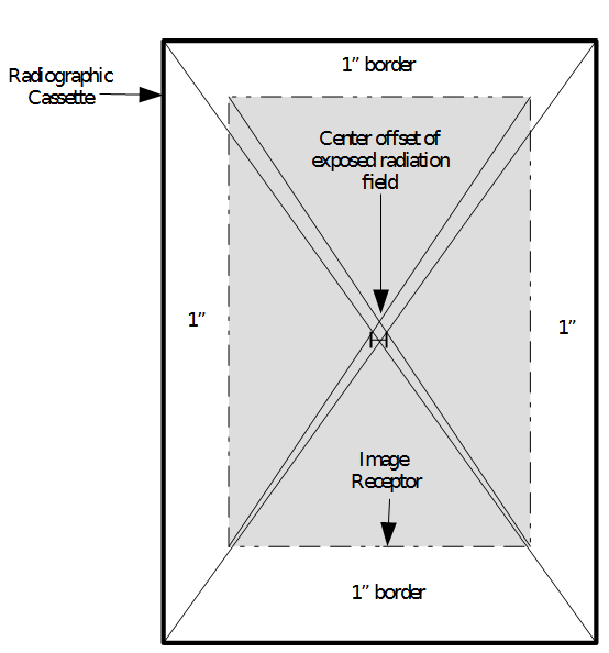
Using a ruler the center of the field light to the center of the exposed film should be less than 2 cm (or 2%). Our example shows 1.12 cm that would pass
8. Use the following formulas:
8a. Length error = L1 + L2
8b. Width error = W1 + W2
8c. Length DIV/SID (% Error) = Length error/SID (12") * 100
8d. Width DIV/SID (% Error) = Width error/SID (12") *100
8e. Total Sum of length and width error = Length DIV/SID (% Error) + Width DIV/SID (% Error)
8f. Center Offset (% error) = center offset/SID (12") * 100 8f-1. For center offset draw lines from corner to corner on the exposure field and corner to corner on the cassette field. Finally, subtract the two center distances.
(3% per dimension; 4% sum error; 2% center offset)
Image Quality Control
Image quality is a characteristic of an image that measures the perceived image degradation as compared to an ideal image. Imaging systems may introduce some amounts of distortion or artifacts in the signal, so the quality assessment is an important problem. For example, comparing an original image factors which must be evaluated such as:
- Sharpness or detail of an image.
- Noise or graininess in film and pixel image.
- Dynamic range or light exposure range.
- Tone reproduction or illuminance
- Contrast or gamma which are varying shades of grey.
- Color accuracy
- Distortion
- Vignetting
- Exposure accuracy
- Lateral chromatic aberration. Also called "color fringing", including purple fringing
- Lens flare
- Artifacts or low quality images
Test Tools
Fluke Biomedical R/F QC Phantom and Fluoroscopic System Resolution Test Tool.
High-Contrast

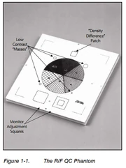
RF/QC Phantom by Fluke Biomedical for low and high contrast resolution verification.
That area where the degree of difference between black and white approaches the maximum.
Procedure
1. Place the line-pair phantom on the table. It should be placed at a 45-degree angle to the grid lines and raster lines of the TV system.
2. At low kVp (ABS with nothing other than the line-pair phantom in the field), determine the maximum line-pair resolution for all available field sizes.
3. It may be necessary to alter the brightness and contrast settings on the TV monitor to optimize the display for the visualized object.
4.Resolution should be at or above 1.2 lp/mm for a 22 cm (9″) FOV and 1.7 lp/mm for a 15 cm (6″) FOV.
5. Indicate pass or fail on PCRI form.
Low-Contrast
A radiographic image that shows many shades of gray
Procedure
1. Place the low-contrast phantom on the table. The thicker aluminum pieces should be on top.
2. Initiate a fluoroscopic exposure under ABS control.
3. On the 15 cm (6″) FOV, the three smallest holes should be visible. It may be necessary to alter the brightness and contrast settings on the TV monitor to optimize the display for the visualized object.
4. Indicate pass or fail on PCRI form.
Mesh (Spatial)


A Mesh (Spatial) test by Fluke Biomedical
The spatial resolution of the fluoroscopic system shall be measured using a test tool composed of a line pair plate with discreet line pair groups and a maximum lead foil thickness of 0.1 mm or an equivalent device. The minimum spatial resolution at the center of the beam for a 6 inch FOV is 2 line pairs per mm. The minimum spatial resolution for all other FOVs shall be determined by the following equation:
![{\displaystyle 2lp/mmx(6inches/sizeofthe[[FieldofView,X-ray|FOV]]used)=minimumnumberoflp/mm.}](https://services.fandom.com/mathoid-facade/v1/media/math/render/svg/96a08a4295aab4bf209f2783dc9ea572d6929a3d)
Procedure
1. Place the low-contrast phantom on the table.
2. Initiate a fluoroscopic exposure under ABS control.
3. These 7½” square plastic plates each have a 7” square area containing 8 groups of copper or brass mesh screening in the following mesh-size ranges: 16 - 60 lines/inch or 30 - 100 lines/inch or 60 - 150 lines/inch.
4. Indicate pass or fail on PCRI form.
(Note: a hard drive is a handy alternative tool to test mesh and other patterns)
Pin Hole


A hard drive is a great alternative tool used for multiple quality assurance checks: A. Pin Hole Test B. Mesh Test C. Dark Contrast D. Light Contrast
The pin hole test of the fluoroscopic system shall be measured using a test tool composed of a circular pattern inside a larger circle. The minimum pinhole resolution is that the inner circle remains within the larger circle and has no vignetting.
Procedure
1. Place the hard drive or pinhole phantom on the table.
2. Initiate a fluoroscopic exposure under ABS control.
3. The inner circle remains within the larger circle.
4. Indicate pass or fail on PCRI form.
(Note: a hard drive is a handy alternative tool to test mesh and other patterns)
Automatic Brightness Control
The range of body part thicknesses and composition encountered in fluoroscopic imaging is quite large. Automatic Brightness Control (ABC) is used to keep the brightness of the displayed image at a constant level during examinations. It involves the adjustment of the kV and mA automatically depending on the part of the anatomy being examined. ABC systems are generally designed to operate between minimum (e.g. 70 kV) and maximum (e.g. 120 kV) kilovoltages.
Test Frequency
Semi-Annually
SID
12”
Test Tools
A Fluke Biomedical R/F QC phantom
Procedures
1. Use R/F QC phantom to verify mesh, bar at different magnifications and densities.
| MAG | BAR | MESH |
| 12" | 3 lines | <1.5mm |
| 9" | 3 lines | <20/24mm |
| 6" | 3 lines | <24/35mm |
2. Verify different contrast colors and record pass or fail.
3. Use Fluoro Resolution phantom to verify mesh (L/in).
4. Count mesh and record pass or fail.
Kilovoltage Verification
The Kilovoltage Verification (KvP) measures noninvasive the electronic x-ray tube voltage test to assure that the tube voltage set on the radiographic equipment display is correct.
Test Frequency
Semi-Annually
SID
12”
Technique Factors
- mA: .5 mA, 1.0 mA, 2.0 mA, 3.0 mA, and 4.0 mA
- kVp: 50 kVp, 80 kVp, and 120 kVp
Test Tools
A X-ray Quality Assurance meter (e.g. RTIs Piranha or Barracuda)
Procedures
1. Place a QA meter upside down on top of table.
2. Set the Spot film and SID to 12” (highest position) then lock in place.
3. Take a series of six shots without any filtration at .5mA, 1.0mA, 2.0mA, 3.0mA, and 4.0mA, settings. Additionally, these five series of shots will be performed at 50kVp, 80kVp, and 120kVp, stationary kVp settings.
4. Measure each exposure in kVp and record. As a rule of thumb, the allowable mA tolerance is +/- 5% and kVp +/- 4.
MilliAmperage Verification
(WARNING: LETHAL VOLTAGES PRESENT)
The MilliAmperage (mAs) Verification measures invasive the electronic x-ray mAs test to assure that the tube amperage in mA set on the radiographic equipment display is correct.
Test Frequency
Semi-Annually
SID
12”
Technique Factors
- mA: .5 mA, 1.0 mA, 2.0 mA, 3.0 mA, and 4.0 mA
- kVp: 50 kVp, 80 kVp, and 120 kVp
- Time: .500
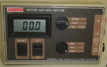

A Keithley mA/mAs meter
Test Tools
A mAs meter
Procedures
1. Remove the high voltage generator cover and locate the mA test points.
2. Set the Spot film and SID to 12” (highest position) then lock in place.
3. Take a series of five shots without any filtration at .5 mA, 1.0 mA, 2.0 mA, 3.0 mA, and 4.0 mA settings. Additionally, these five series of shots will be performed at 60 kVp, 80 kVp, and 120 kVp, stationary kVp settings.
4. Measure each exposure in mA and record. As a rule of thumb, the allowable mA tolerance is +/- 5% and kVp +/- 4.
Entrance Skin Exposure Rates
ESE is the measurement of radiation "dose" output at various anatomical regions for common X-ray examinations, including fluoroscopic and conventional radiology. Traditionally, we must compare the facility’s entrance exposure for chest, abdomen, skull and extremities examinations. These units are measured in milli Roentgen (mR) / minute.
Phantoms
| Chest | Abdomen/lumbar | Skull | Extremity |
 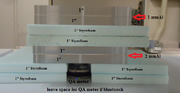 Chest Setup: Image Intensifier/SFD 1" Acrylic 1 mm Al 1" Acrylic 2" Air Gap/Styrofoam 1" Acrylic 2 mm Al 1" Acrylic 2" Styrofoam w/ion chamber on table top Table Top X-Ray Tube |
  Abdomen/lumbar Setup: Image Intensifier/SFD 4.5 mm Al 2.75" X 12" to simulate spine 7" Acrylic 2" Styrofoam w/ion chamber on table top Table Top X-Ray Tube |
  Skull Setup: Image Intensifier/SFD 1" Acrylic 1 mm Al 4" Acrylic 2 mm Al 1" Acrylic 2" Styrofoam w/ion chamber on table top Table Top X-Ray Tube |
  Extremity Setup: Image Intensifier/SFD 1" Acrylic 2 mm Al 1" Acrylic 2" Styrofoam w/ion chamber on table top Table Top Tube |
Fluoroscopic
Test Frequency
Semi-Annually
SID
12”
Technique Factors
32 mAs, phantoms (Acrylic an Styrofoam)
Test Tools
A X-ray Quality Assurance meter (e.g. RTIs Piranha or Barracuda)
Procedures
1. Place a QA meter on top of table.
2. Set the SID to 12” and lock in place.
3. 2. Set mode to "Automatic".
4. Set "Magnification" (Mag) to (12″) FOV, 6″ FOV, and 3' FOV.
5. Take a series of four shots with various phantoms (chest, abdomen, Skull, and Extremity) and using various grid positions:
| Phantom | Mode | Mag | Grid Position |
|---|---|---|---|
| Chest | Auto | 12" | Grid In |
| Auto | 6" | Grid In | |
| Auto | 12" | Grid Out | |
| Auto | 6" | Grid Out | |
| Abdomen | Auto | 12" | Grid In |
| Auto | 6" | Grid In | |
| Auto | 12" | Grid Out | |
| Auto | 6" | Grid Out | |
| Skull | Auto | 12" | Grid In |
| Auto | 6" | Grid In | |
| Auto | 12" | Grid Out | |
| Auto | 6" | Grid Out | |
| Extremeity | Auto | 12" | Grid In |
| Auto | 6" | Grid In | |
| Auto | 12" | Grid Out | |
| Auto | 6" | Grid Out |
6. Measure each kVp, mA exposures and milliRoentgen (mR) / minute and record.
Spot Film
Test Frequency Semi-Annually
SID
12”
Technique Factors
32 mAs, phantoms (Acrylic an Styrofoam)
Test Tools
A X-ray Quality Assurance meter (e.g. RTIs Piranha or Barracuda)
Procedures
1. Place a QA meter on top of table.
2. Set the SID to 12” and lock in place.
3. 2. Set mode to "Automatic".
4. Set "Magnification" (Mag) to (12″) FOV, 6″ FOV, and 3' FOV.
5. Take a series of four shots with various phantoms (chest, abdomen, Skull, and Extremity) and using various grid positions:
| Phantom | Mode | Mag | Grid Position |
|---|---|---|---|
| Chest | Auto | 12" | Grid In |
| Auto | 6" | Grid In | |
| Auto | 12" | Grid Out | |
| Auto | 6" | Grid Out | |
| Abdomen | Auto | 12" | Grid In |
| Auto | 6" | Grid In | |
| Auto | 12" | Grid Out | |
| Auto | 6" | Grid Out | |
| Skull | Auto | 12" | Grid In |
| Auto | 6" | Grid In | |
| Auto | 12" | Grid Out | |
| Auto | 6" | Grid Out | |
| Extremeity | Auto | 12" | Grid In |
| Auto | 6" | Grid In | |
| Auto | 12" | Grid Out | |
| Auto | 6" | Grid Out |
6. Measure each kVp, mA exposures and milliRoentgen (mR) / minute and record.
Action Required
Action Required is where the inspector can record any notes.
Form
- DD 2164 - X-RAY VERIFICATION/CERTIFICATION WORKSHEET
- AF Form 2026 - Post-Calibration Radiation Inspection Record Fluoroscopic (31 March 2003)
Reference
- ↑ Dept New York Health. "Guide for Radiation Safety/Quality Assurance Programs". Accessdate 1/6/2014. https://www.health.ny.gov/environmental/radiological/radiation_safety_guides/fluoroscopic_equipment.htm